Permeable paving roof runoff guidance flags inlet scour and storage needs
The Drainage Designers advises routing roof water through a gully or channel before permeable paving, with storage sized for roof and driveway rainfall.
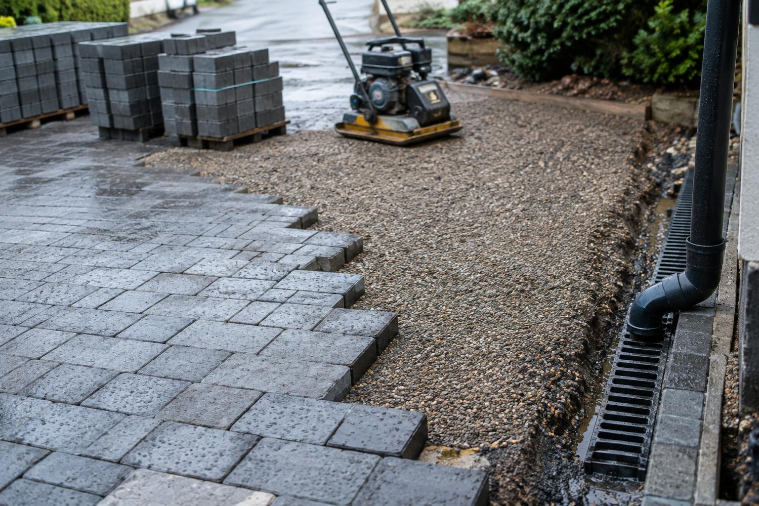
Key facts
- The Drainage Designers advises using a spreader or channel to prevent concentrated roof runoff damaging permeable paving.
- The guidance says drainage sizing must account for rainfall on both the roof and driveway.
- Its worked example gives 3 cubic metres of runoff from a 60 square metre roof receiving 50 mm rainfall.
- Aggregate with 30% void space stores roughly 0.3 cubic metres of water per cubic metre, according to the guidance.
- The guidance recommends lined systems with controlled outfalls where clay soils prevent effective infiltration.
- The Drainage Designers recommends monthly surface sweeping and annual brushing or vacuuming of paving joints.
Guidance warns against concentrated downpipe discharge
The Drainage Designers advises routing roof runoff through a spreader, gully or channel before it reaches permeable paving, warning that a concentrated downpipe discharge can scour joints and wash out bedding. Its company guidance, last updated on 11 October 2026, addresses connections between roofs and driveways; it is design advice from the firm, rather than a regulatory announcement.
Permeable paving allows rainwater to enter through gaps between blocks and collect in an aggregate sub-base, a layer of stone that provides temporary water storage beneath the surface. Where ground conditions allow, the stored water then infiltrates, or seeps into, the soil. The firm describes this sequence as capture, storage and infiltration, with each stage performing a distinct drainage function.
For a surface-fed connection, the guidance proposes placing a channel or gully at the paving edge to receive the downpipe flow and distribute it across the joints. It also identifies a connection into a below-ground aggregate reservoir as an option. In either arrangement, the firm says the paving, storage layer and soil infiltration rate must accommodate the additional roof water.
The inlet warning has implications for the construction of the upper paving layers. The guidance specifies joints of 10 to 15 mm filled with small aggregate or grit, above a bedding layer typically 30 to 50 mm thick using 6 mm to 10 mm aggregate or coarse sand. It warns that excessive bedding thickness can cause blocks to settle unevenly.
The firm says slowing roof runoff through the paving and sub-base can reduce peak discharge from a plot and pressure on the public sewer, with water entering the ground over hours rather than seconds. It also describes sediment settling within the layers and some pollutants binding to stone. These are drainage and filtration benefits claimed by the company, not results from a reported monitoring programme.
Keeping those entry points clear forms part of the firm's advice on protecting the system's performance. It recommends monthly sweeping to remove leaves and grit, clearing downpipe traps and channels twice a year, and brushing or vacuuming joints annually. Checks after heavy rainfall should record where water ponds, while overflow outlets should be inspected each autumn; the guidance warns that clogged joints can prevent the surface draining.
Roof catchment adds to driveway storage demand
Storage sizing must account for rainfall on both the roof and the driveway, according to The Drainage Designers. The contributing roof catchment is its footprint, including overhangs, rather than the larger surface area of a pitched roof, because rainfall falls vertically. The guidance gives 50 to 70 square metres as an illustrative footprint for a typical semi-detached house, not a fixed design allowance.
Its worked example applies 50 mm of rainfall to a 60 square metre roof: multiplying 60 square metres by 0.05 metres produces 3 cubic metres of runoff. The source illustrates this with a possible 1 in 100 year storm delivering that depth in an hour. It points designers towards local authority guidance or Met Office rainfall information; 50 mm is not presented as a universal design requirement.
The storage calculation then assumes aggregate with 30% void space, meaning each cubic metre of the sub-base can hold approximately 0.3 cubic metres of water between the stones. Holding 3 cubic metres therefore requires about 10 cubic metres of sub-base. Spread beneath a 30 square metre driveway, that corresponds to around 330 mm depth, according to the firm's example.
That example demonstrates storage for the stated roof runoff volume, rather than a complete calculation for combined roof and driveway rainfall. The guidance also distinguishes storage demand from total runoff: where soil admits water sufficiently quickly, infiltration during drainage reduces the volume that must remain temporarily in the reservoir. Ground performance therefore affects how much aggregate storage the design needs.
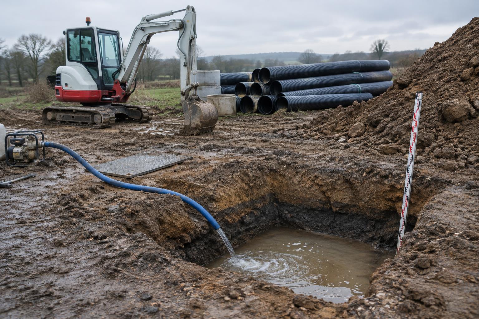
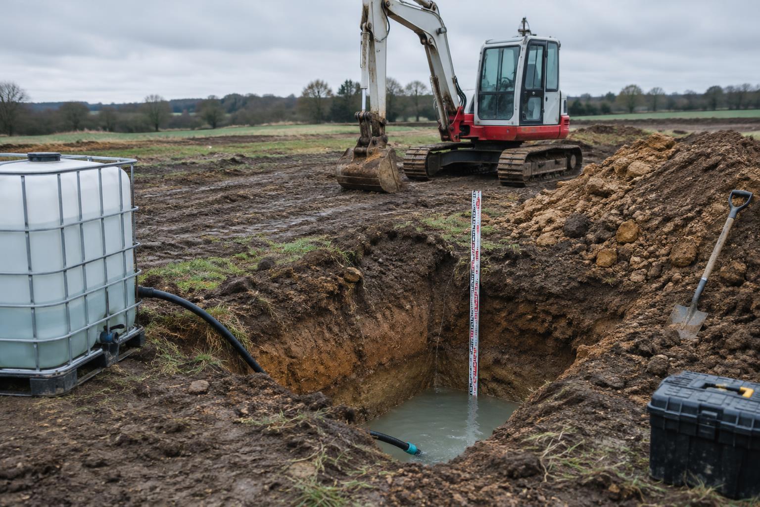
To establish that performance, the firm recommends testing at the proposed sub-base depth by filling a trial pit and measuring the falling water level at least three times. It advises testing in dry conditions and checking groundwater and bedrock depths. Clay may infiltrate at less than 1 mm per hour, it says, requiring a lined system with a controlled outfall rather than reliance on a soakaway.
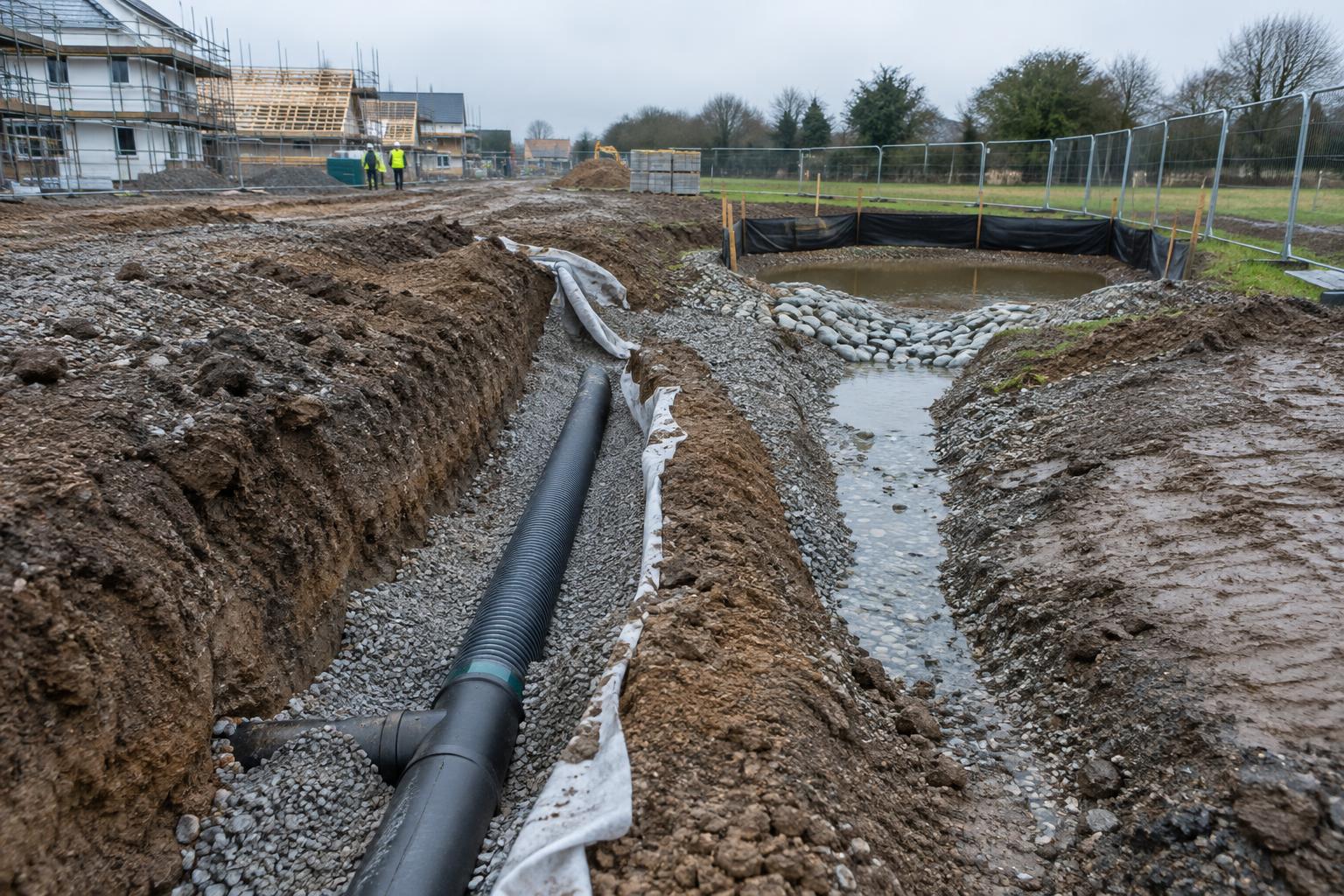
The guidance links usable storage to installation quality as well as dimensions. It specifies clean, open-graded 20 mm to 40 mm crushed stone, compacted in layers no thicker than 150 mm, with a permeable geotextile across the excavation base and sides to prevent soil fines entering the reservoir. Typical excavation is 300 to 500 mm below finished level, depending on storage needs; the firm warns that migrating fines reduce capacity and poor compaction causes settlement and ponding.
Designer links drainage layout to ground conditions
The Drainage Designers recommends check dams or a stepped sub-base where a site's slope could accelerate water movement below the paving. Check dams are barriers that interrupt that flow. The firm's advice makes the shape of the underground reservoir a design consideration, rather than treating it as a continuous layer on every plot.
Contaminated ground presents a separate constraint: the firm proposes a lined arrangement to prevent pollutants entering the soil. It also says it designs schemes around Local Authority and Lead Local Flood Authority requirements, identifying those bodies' requirements as an important consideration for domestic applications.
For flows beyond the system's capacity, the guidance proposes an overflow pipe leading from the reservoir to a soakaway or an approved outfall. A surface water sewer is an option where permission allows, but the firm explicitly advises against connecting the overflow to a foul sewer.
The overflow inlet's elevation determines when that route starts operating. The firm places it slightly above the reservoir's normal operating water level, so it activates when storage is full. It presents this arrangement as protection against water backing up towards the house when very heavy rainfall overwhelms the system.
The destination of excess water also needs to respect neighbouring land. The guidance says designers should not direct overflow onto another property without permission. That adds a boundary constraint to the choice of discharge route, alongside the need to identify an acceptable receiving drainage feature or sewer connection.
Site assessment and maintenance follow design decisions
The guidance identifies a specific groundwater threshold: a water table within 1 metre of the sub-base's underside may restrict infiltration or create a pollution risk. That distance relates to the bottom of the proposed storage layer, rather than the finished driveway surface, making the reservoir's position relevant to the assessment.
At the surface, the firm recommends a fall away from the house of at least 1 in 100. Below ground, it advises keeping the sub-base at least 1 metre from foundations unless a waterproof membrane protects them. These are the firm's stated layout recommendations, not dimensions attributed to a statutory standard.
Basements attract a different recommendation. The guidance calls for at least 2 metres of separation between the system and a basement, or alternatively a lined arrangement with a pumped outfall. This introduces a distinct discharge option for properties where below-ground accommodation affects the available drainage layout.
For existing paving, the firm distinguishes permeable construction from blocks with tight joints containing mortar or kiln-dried sand, which it says are likely impermeable. Its suggested screening check is to pour a glass of water onto the surface: water remaining there may indicate either impermeable construction or a blockage.
Where drainage problems emerge, the firm's frequently asked questions identify joint re-sanding or inspection of the sub-base as possible responses. It warns that leaving problems unresolved can ultimately require blocks to be lifted, distinguishing routine surface attention from remedial work involving access to the layers below.
The assessment also extends to cost and usability. According to the guidance, installation can cost more than conventional paving, while some homeowners find the textured finish less smooth underfoot. The firm identifies these as disadvantages to consider when deciding whether the surface suits a particular property.
Why this matters
For drainage and flood risk professionals, the remaining design choices concern where water can safely travel when the preferred drainage route is unavailable. Boundary permissions, building protection and the receiving outfall can constrain a layout independently of its calculated capacity. The guidance also distinguishes surface symptoms from faults that may need below-ground investigation, making the choice between routine maintenance and more intrusive remedial work relevant to those specifying, approving and managing domestic drainage.
Frequently asked questions
can a roof downpipe discharge onto permeable paving?
The Drainage Designers advises routing roof runoff through a spreader, channel or gully before it reaches permeable paving. Concentrated discharge can erode the joints and wash out bedding. The drainage design must accommodate the additional roof runoff.
how do you size permeable paving drainage for roof runoff?
The Drainage Designers says sizing must include rainfall on both the roof and driveway, alongside the soil’s infiltration rate. Use the roof footprint, including overhangs, to calculate roof runoff rather than the larger surface area of a pitched roof.
how much runoff does a 60 square metre roof produce?
A 60 square metre roof receiving 50 mm of rainfall produces 3 cubic metres of runoff in The Drainage Designers’ worked example. The calculation multiplies the roof footprint by rainfall depth: 60 square metres × 0.05 metres.
how much water can a permeable paving sub-base store?
According to The Drainage Designers, aggregate with 30% void space holds roughly 0.3 cubic metres of water per cubic metre. Storing 3 cubic metres therefore requires about 10 cubic metres of aggregate sub-base, the stone reservoir beneath the paving.
can permeable paving work on clay soil?
The Drainage Designers recommends a lined system with a controlled outfall where clay prevents effective infiltration, meaning water soaking into the ground. Its guidance says clay infiltration rates may fall below 1 mm per hour. Soil testing establishes whether infiltration is viable.
where should permeable paving overflow drain to?
The Drainage Designers identifies a soakaway or approved outfall as an overflow destination, including a surface water sewer where permitted. It advises setting the overflow slightly above the sub-base’s normal operating water level and says it must not connect to a foul sewer.
how often should permeable paving be cleaned?
The Drainage Designers recommends monthly surface sweeping and annual brushing or vacuuming of joints. Clear downpipe traps and channels twice a year, inspect the overflow outlet each autumn and check for standing water after heavy rainfall.
Related coverage